
Engineering Guide
Draw Latches: Complete Guide to Types, Load Ratings & Industrial Applications
All draw latch types compared: over-center, adjustable, spring-loaded, concealed, hook & loop, rotary, slam-action. Load ratings 50-5,000 N. Sizing calculations, material specs, vibration test data & application matrix. 21 models from a 35-year factory. Get quote →
Quick Answer
A draw latch pulls two surfaces together under tension — sealing gaskets, preventing rattling, and securing enclosure doors during vibration. The 7 main types: over-center (self-locking, best for vibration), adjustable (fine-tunable compression), spring-loaded (constant tension), concealed (tamper-resistant), hook & loop (simplest), rotary (compact), and slide-action/slam (fastest). Load ratings range from 50 N to 5,000+ N. Skip to the comparison table.
1. What Is a Draw Latch?
A draw latch (also called a draw catch, draw-pull latch, or tension latch) is a two-piece fastening mechanism that creates tension between two surfaces. One piece — the latch body with lever and hook — mounts to the door, lid, or panel. The other piece — the keeper (also called a catch, strike, or loop) — mounts to the frame or body.
When the lever is closed, the hook engages the keeper and the mechanical linkage pulls the two surfaces together. This clamping action compresses any gasket or seal between the surfaces, creating an environmental barrier against dust, water, and contaminants.
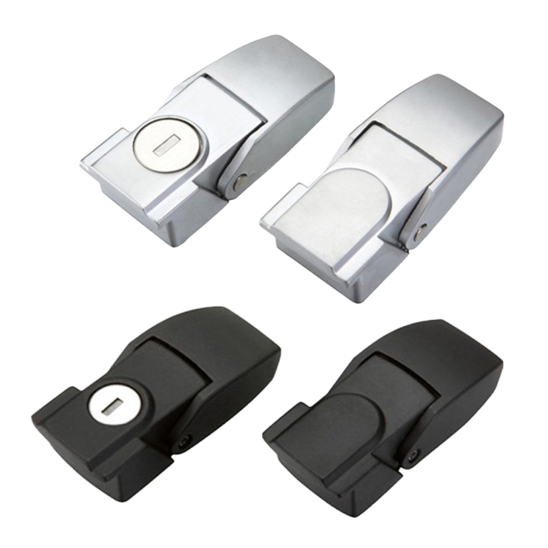
Draw latches are standard hardware for toolboxes, flight cases, industrial enclosures, equipment covers, medical device housings, and any application where two surfaces must be held tightly together under tension. They differ from simple hasps or cam locks in that they actively pull the door toward the frame rather than merely preventing it from swinging open.
Key terminology:
- Draw — the pull-up distance; how far the latch pulls the surfaces together (typically 5–15 mm)
- Clamping force — the tension created when closed (measured in Newtons, kgf, or lbf)
- Over-center — the geometric dead point that self-locks the mechanism against opening
- Keeper / Strike — the mating piece that the hook engages
- Grip range — the adjustable distance between latch and keeper that accommodates different panel gaps
Hengchieh manufactures 21 draw latch and toggle latch models in zinc alloy and stainless steel, covering all 7 types described in this guide.
2. How Draw Latches Work
All draw latches convert lever action into linear clamping force. The operator pushes or pulls a lever; the lever’s mechanical linkage translates that motion into tension that draws the two mounting surfaces together. The specific mechanism varies by type, but the fundamental physics is the same: mechanical advantage multiplies a small operator input force into a large clamping output.
The Over-Center Principle
The most important draw latch mechanism is the over-center toggle. When the lever passes through a geometric dead point (where the pivot, base attachment, and hook engagement are collinear), the mechanism self-locks. Any external force trying to open the latch must first push the lever back over center — which requires deliberate, directed force that vibration cannot generate.
Manufacturer test data: At our factory, we test over-center draw latches on a vibration table at 10–50 Hz, 1–5g acceleration for 1 hour. Over-center latches consistently hold. Non-over-center hook latches pop open within minutes at 2g acceleration. If your application vibrates, over-center is non-negotiable.
For a deep-dive into the over-center mechanism with phase diagrams and force calculations, see our toggle latch engineering guide.
Clamping Force Calculation
The clamping force a draw latch generates depends on three factors: (1) the lever’s mechanical advantage ratio, (2) the hook-to-keeper engagement angle, and (3) the spring preload (if applicable). The relationship is:
Fclamp = Foperator × MA × cos(θ)
Where MA is the mechanical advantage (typically 3:1 to 8:1 for industrial draw latches) and θ is the hook engagement angle. This means a 50 N hand force with a 6:1 lever generates approximately 250–300 N of clamping force at the gasket face.
3. 7 Types of Draw Latches
Type 1: Over-Center Draw Latch (Toggle Latch)
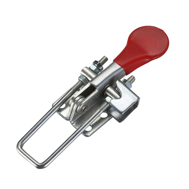
The most common industrial draw latch. A lever pivots on a base, driving a hook into a keeper. The over-center geometry self-locks the mechanism against vibration-induced opening. Available in pull-action (hook pulls toward base) and push-action (lever pushes catch downward) configurations.
- Clamping force: 100–2,000 N depending on size
- Draw distance: 5–15 mm
- Vibration safe: Yes (self-locking past dead center)
- Typical use: Flight cases, toolboxes, equipment covers, industrial enclosures
Type 2: Adjustable Draw Latch
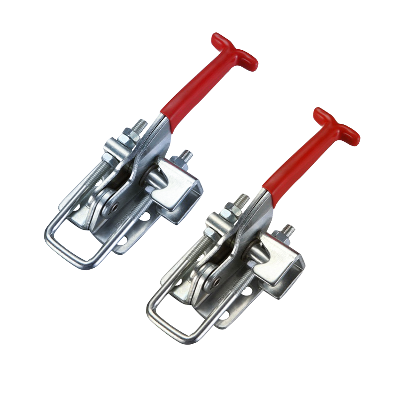
Features a threaded hook or turnbuckle that allows the draw distance and clamping force to be adjusted after installation. Turn the hook clockwise to increase tension, counterclockwise to decrease. Essential for gasket applications where compression needs fine-tuning — especially on welded enclosures with normal manufacturing tolerances of ±1–2 mm.
- Adjustment range: Typically 5–10 mm of thread travel
- Clamping force: 100–1,500 N (adjustable)
- Typical use: Sealed enclosures, gasket compression, welded cabinets with variable tolerances
Need help selecting draw latches?
Send us your enclosure dimensions, gasket type, and operating environment — we’ll calculate the required clamping force and recommend specific models within 24 hours.
Get a RecommendationType 3: Spring-Loaded Draw Latch
Incorporates an internal or external spring that maintains constant tension on the hook, even as the door vibrates or the gasket relaxes over time. The spring compensates for thermal expansion, gasket creep (EPDM loses 10–15% of height over 5 years), and manufacturing tolerances. This “set and forget” capability makes spring-loaded draw latches ideal for maintenance-free installations.
- Spring force: 20–80 N constant tension
- Clamping force: 200–1,000 N
- Typical use: HVAC panels, engine covers, vibrating machinery, outdoor enclosures
Type 4: Concealed Draw Latch
Mounts behind the panel surface — no visible hardware on the exterior. Operated by pushing a hidden lever, squeezing tabs, or using a tool (screwdriver, hex key) through a small access hole. Provides both clean aesthetics and tamper resistance. Critical for applications where external hardware would be a vandalism risk or compromise a sterile/cleanroom surface.
- Clamping force: 50–500 N
- Typical use: Medical equipment, retail displays, secure enclosures, architectural panels, military housing
Type 5: Hook & Loop Draw Latch
The simplest draw latch design: a hook on the lid engages a loop (bail) on the body. No over-center mechanism — the hook drops into the loop and relies on gravity or a secondary padlock to stay closed. Inexpensive and easy to install, but provides no vibration resistance without a padlock or safety clip.
- Clamping force: Low (gravity-dependent)
- Typical use: Chest-style toolboxes, storage trunks, basic enclosure covers, agricultural equipment
Type 6: Rotary Draw Latch
Uses a rotating cam or quarter-turn mechanism instead of the traditional toggle linkage. A quarter-turn of the handle engages or disengages the latch. More compact than toggle-type draw latches and ideal for tight spaces where a standard lever would interfere with adjacent components. Some rotary draw latches include a detent mechanism for vibration resistance.
- Clamping force: 100–800 N
- Typical use: Automotive panels, avionics enclosures, compact equipment, machine access doors
Type 7: Slide-Action (Slam) Draw Latch
Engages automatically when the door slams shut — no manual lever operation required. A spring-loaded catch grabs the keeper as the door closes. To open, you lift or push a release lever. The fastest operation time of any draw latch type, making it ideal for high-frequency access panels on production lines.
- Clamping force: 50–300 N
- Typical use: Packaging machinery, conveyor covers, high-frequency access panels, food processing
4. Draw Latch Comparison Table
All 7 draw latch types compared side by side:
| Draw Latch Type | Clamping Force | Vibration Safe? | Adjustable? | Lockable? | FOB Price |
|---|---|---|---|---|---|
| Over-Center (Toggle) | 100–2,000 N | Yes | No | Padlock hole | $1.50–$8 |
| Adjustable | 100–1,500 N | Optional | Yes (5–10 mm) | Padlock hole | $2–$10 |
| Spring-Loaded | 200–1,000 N | Yes | Self-compensating | Some models | $3–$12 |
| Concealed | 50–500 N | Varies | Some models | Tool-actuated | $3–$15 |
| Hook & Loop | Low (gravity) | No | No | Padlock hasp | $0.50–$3 |
| Rotary | 100–800 N | With detent | No | Some models | $2–$10 |
| Slide-Action (Slam) | 50–300 N | Spring-held | No | Varies | $2–$8 |
Recommendation: For most industrial enclosures, start with an over-center draw latch (best all-around). Upgrade to adjustable if your enclosure has gaskets that need compression tuning. Use spring-loaded for maintenance-free outdoor installations.
5. Load Ratings & Sizing Calculations
Correctly sizing draw latches prevents two failure modes: under-sizing (latch cannot maintain seal, gasket leaks) and over-sizing (excessive force deforms gasket, reducing service life and increasing operator fatigue).
Step-by-Step Sizing
- Calculate gasket compression force: For standard EPDM gaskets, multiply the gasket perimeter (in cm) by 3–7 N/cm. Example: 2,000 mm perimeter = 200 cm × 5 N/cm = 1,000 N total
- Add pressure differential: If the enclosure has positive or negative internal pressure, add this force. For a 600×400 mm door at 100 Pa internal pressure: 0.24 m² × 100 Pa = 24 N
- Add gravity component: For vertically-mounted doors, add the door weight component: W × sin(α) where α is the door angle from vertical
- Divide by number of latches: Distribute force among 2–6 latches depending on door size
- Apply safety factor: 2× for static applications, 3–4× for vibrating equipment, 5× for safety-critical (overhead covers)
| Enclosure Size | Gasket Length | Latches Needed | Min. Per-Latch Rating |
|---|---|---|---|
| 300 × 200 mm | 1,000 mm | 2 | 150–350 N |
| 600 × 400 mm | 2,000 mm | 4 | 150–350 N |
| 800 × 600 mm | 2,800 mm | 4–6 | 200–500 N |
| 1200 × 800 mm | 4,000 mm | 6–8 | 300–700 N |
Values assume EPDM gasket at 5 N/cm, IP65 target, 2× safety factor. For vibrating applications, multiply minimum rating by 1.5–2×.
6. Materials & Corrosion Resistance
| Material | Salt Spray (hrs) | Strength | Cost | Best Application |
|---|---|---|---|---|
| Zinc-Plated Steel | 48–120 | High | $ | Indoor, dry environments |
| Zinc Alloy (Zamak) | 120–240 | Medium-High | $$ | Standard industrial |
| 304 Stainless Steel | 500+ | High | $$$ | Outdoor, food processing |
| 316 Stainless Steel | 1,000+ | High | $$$$ | Marine, chemical, coastal |
| Glass-Filled Nylon | N/A (immune) | Medium | $$ | Non-conductive, lightweight |
For a detailed comparison between zinc alloy and stainless steel, see our zinc alloy vs stainless steel lock guide. For marine and chemical environments, 316 stainless steel is non-negotiable — the molybdenum content provides critical pitting resistance that 304 lacks in chloride environments (per ASTM B117 salt spray testing).
7. Industrial Applications Matrix
| Application | Recommended Type | Material | Min. Rating | Key Feature |
|---|---|---|---|---|
| Truck toolbox | Over-center | 304 SS | 200 N | Vibration + road salt |
| Flight case | Over-center | Zinc steel | 100 N | Padlock hole |
| IP65 enclosure | Adjustable | 304/316 SS | 300 N | Gasket compression tuning |
| Medical equipment | Concealed | 316 SS / Nylon | 100 N | Tamper-proof, cleanable |
| HVAC panel | Spring-loaded | Zinc alloy | 200 N | Self-compensating |
| Production line cover | Slide-action (slam) | 304 SS | 150 N | Auto-engage, fast access |
| Vibrating machine | Over-center + spring | Steel / SS | 500 N | 3–4× safety factor |
| EV charging cabinet | Over-center + lockable | 316 SS | 300 N | Anti-vandal, IP66+ |
For EV charging and battery enclosure applications specifically, our EV charging cabinet hardware guide covers compliance requirements (UL 2594, IEC 61851) and multi-point locking configurations. For truck toolbox lock replacement, we compare draw latches against T-handles, paddle latches, and cam locks.
8. Draw Latches vs Other Latch Types
| Feature | Draw Latch | Compression Latch | Paddle Latch | Cam Lock |
|---|---|---|---|---|
| Mounting | Surface | Flush (panel cutout) | Flush (recess) | Through-hole |
| Clamping force | 50–5,000 N | 200–1,500 N | Low–Medium | None |
| Gasket compression | Excellent | Excellent | Limited | None |
| Vibration resistance | Excellent (over-center) | Good | Good | Poor |
| Profile | Protruding | Flush | Flush | Low-profile |
| Best for | Lids, covers, cases | Sealed cabinets | Panels, toolboxes | Drawers, cabinets |
When to choose draw latches over compression latches: Use draw latches when the door or lid opens fully (180°), when you need maximum clamping force (>1,000 N), when surface mounting is preferred over panel cutouts, or when the latch must be visible for quick-release identification. Use compression latches when a flush profile is required, when the door is side-hinged on a sealed cabinet, or when aesthetics demand no protruding hardware.
For paddle latches, the primary advantage is the recessed flush-mount profile that prevents snagging. For cam locks, simplicity and low cost make them ideal where sealing is not required.
9. Installation & Maintenance
Installation Best Practices
- Mark mounting positions — Use a template or measure from a datum edge. Ensure the latch centerline aligns with the keeper centerline within ±1 mm
- Drill pilot holes — Use the manufacturer’s recommended drill size for through-bolts or self-tapping screws
- Mount the keeper first — Fix the keeper (strike) to the frame, then position the latch body on the door/lid to match
- Check draw distance — Close the latch and verify the hook engages the keeper with the correct draw. For adjustable models, set to mid-range first
- Test gasket compression — Use feeler gauges or pressure-indicating film to verify uniform compression around the perimeter
- Apply thread-locking compound — On vibrating equipment, use medium-strength (blue) threadlocker on mounting screws
Maintenance Schedule
- Every 6 months: Inspect for corrosion, verify latch engagement, check gasket condition
- Annually: Lubricate pivot points (light machine oil or dry PTFE spray), re-torque mounting screws, adjust compression on adjustable models
- Every 3–5 years: Replace gaskets (EPDM loses 10–15% of height from compression set), inspect hook and keeper for wear
10. Frequently Asked Questions
What is a draw latch?
What is the difference between a draw latch and a toggle latch?
How do I calculate the clamping force I need?
Can draw latches be locked?
Adjustable or non-adjustable?
What load rating for vibrating equipment?
Browse Our Draw Latch & Toggle Latch Range
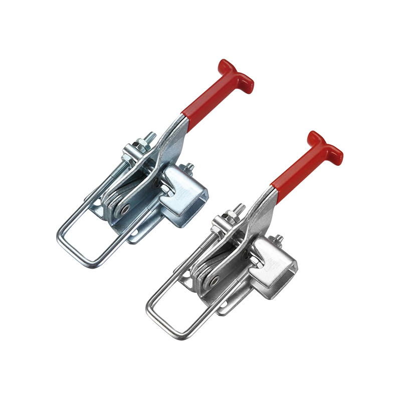
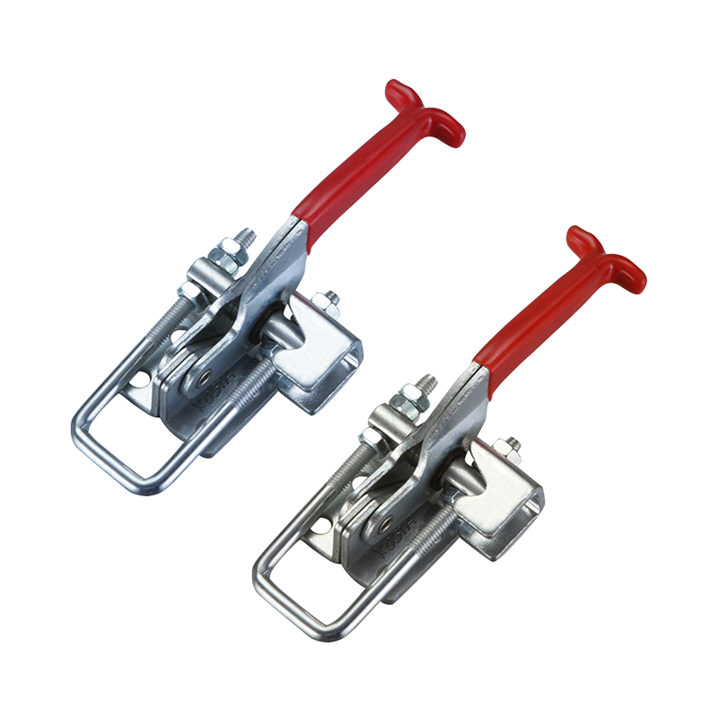
Hengchieh manufactures 21 toggle latch and draw latch models in zinc alloy, zinc-plated steel, and stainless steel. Over-center, adjustable, spring-loaded, and lockable configurations.

Related Guides
Toggle Latch Engineering Guide
Over-center mechanism deep-dive, vibration testing
Compression Latches Guide
IP ratings, gasket compression, flush-mount types
Paddle Latches Guide
Flush-mount, NEMA rated, truck toolbox types
Types of Toolbox Locks
T-handle, paddle, cam, compression compared
EV Charging Cabinet Hardware
Latches, locks & enclosure solutions for EV chargers
Zinc Alloy vs Stainless Steel
Material comparison for industrial hardware
Draw Latch Manufacturer — 21 Models, OEM Available
Selection guide, load ratings, materials, MOQ & factory direct pricing